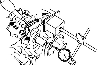
Note:
- Standard axial clearance of the crankshaft: 0.08-0.29 mm.
- Maximum permissible axial clearance of the crankshaft: 0.30 mm.
Dimensions of thrust half rings:
- Standard size: 2.500-2.550 mm.
- Repair size +0.25: 2.625-2.675 mm.
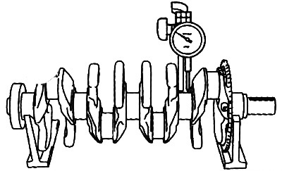
2. Using V-blocks and a dial gauge, measure the runout of the crankshaft main journals. If the measured value exceeds the limit (0.10 mm), replace the crankshaft with a new one.

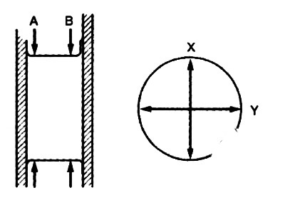
3. Check the diameter of the main and connecting rod journals of the crankshaft in four positions - in two directions (X and Y) at two points (A and B), as it shown on the picture. If the measured values are out of specification or if the amount of ovality (difference between X and Y values) exceeds the maximum permissible value, bore the crankshaft journal to the repair size.

Note:
- Standard diameter of the main journal: 49.980-50.000 mm.
- Maximum permissible ovality of the main neck: 0.005 mm.
- Standard crankpin diameter: 49.980-50.000 mm.
- Maximum allowable ovality of the connecting rod journal: 0.005 mm.
4. Check the oil clearance of the camshaft main journal:
- Install thrust washers, upper main bearing shells and crankshaft to cylinder block.
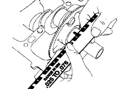
- Place a piece of a round probe on the neck.
- Install the lower main bearing shell and lower cylinder block.
- Tighten the cylinder block bottom bolts.
- Loosen the bolts and remove the lower part of the cylinder block.
- Measure the main bearing oil clearance at the most flattened part of the dipstick. If the measured value exceeds the limit, replace the main bearing shell or bore the main journal and use oversized bearing shells to achieve the correct oil clearance.

Note:
- Standard crankshaft journal oil clearance: 0.016-0.039 mm.
- Maximum permissible oil clearance of the crankshaft main journal: 0.084 mm.
Main bearing shell sizes:
- Standard size: 2.489-2.510 mm.
- Repair size +0.25: 2.614-2.617 mm.
- Repair size +0.50: 2.739-2.742 mm.
