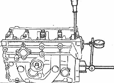
Checking the axial clearance of the crankshaft with a micrometer
2. Push the crankshaft all the way back and set the micrometer to zero. Then, pull the crankshaft as far forward as possible and check the reading on the micrometer. The distance it moves is the axial clearance. If it is more than indicated in Specifications, check the crankshaft thrust surfaces for wear. If there is no wear, new main bearings should correct the end play.
3. If no micrometer is available, feeler gauges cannot be used because the thrust flanges on the center main bearing shell are only on the seat side, not on the cap.
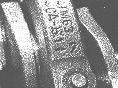
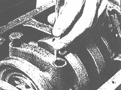
4. Loosen each of the main bearing cap bolts at the same time by a quarter until they can be removed by hand. Check the main bearing caps to see if they are marked with their locations. They are usually listed sequentially from front to rear of the engine. If they are not, mark them with stamped numbers or a punch (photo). Main bearing caps have an arrow that points to the front of the engine (photo).

Most main bearing caps are factory numbered and have an arrow pointing towards the front of the engine | 
If the main covers are not identified by numbers and lines, mark them with a center punch to indicate the position and direction of installation |
5. Tap the caps lightly with a soft-faced hammer, then pry them off the engine block. If necessary, use the main bearing cap mounting bolts as a lever to remove the cap. Try not to skip the bearing shell if it comes out with the cover.

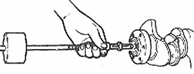
Removing the release bearing from the crankshaft (models with manual transmission)
6. Carefully remove the crankshaft from the engine. Invite an assistant, as the crankshaft is very heavy. With the bearing shells in place on the engine block and main bearing cap, return the caps to their respective positions on the engine block and tighten the bolts in the direction of the arrow. On manual transmission models, remove the release bearing from the end of the crankshaft using a slide hammer (the tool is in special workshops).
