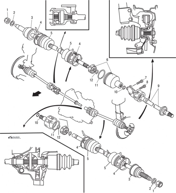
Pic. 9.29. Details and arrangement of shafts on vehicles with a manual transmission: 1 - nut; 2 - washer; 3 - outer CV joint; 4 - collar; 5 - protective cover; 6 - CV joint from the side of the differential; 7, 8 - bolts for fastening the support of the intermediate shaft; 9 - intermediate shaft; 10, 11 - retaining rings; 12 - thrust ring
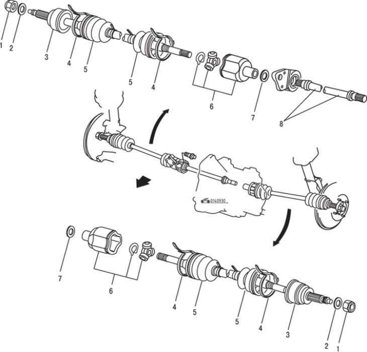
The main elements and the location of the shafts on vehicles with manual and automatic transmissions are shown in fig. 9.29, 9.30.

Pic. 9.30. Parts and arrangement of shafts on vehicles with automatic transmission: 1 - nut; 2 - washer; 3 - outer CV joint; 4 - collar; 5 - protective cover; 6 - SHRUS type tripod; 7 - retaining ring; 8 - intermediate shaft
To remove the shaft, follow these steps.
Raise the front of the car, secure it on stands, remove the front wheels and mudguards, drain the fluid from the gearbox.
With a screwdriver inserted through the caliper, block the brake disc from turning and unscrew the hub nut. This nut is very tight. When installing, a new nut must be used.
Disconnect the stabilizer link, unscrew the ball joint, nuts and bolts of the steering knuckle, disconnect the front suspension strut from the ball joint.

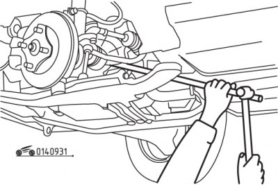
Pic. 9.31. Using a spudger to disconnect a drive shaft from a manual transmission

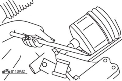
Pic. 9.32. Using a chisel to disconnect the drive shaft from the automatic transmission
Remove the inner end of the drive shaft or intermediate shaft from the gearbox by inserting a spudger between the gearbox housing and the inner CV joint housing (pic. 9.31). With light blows on the mounting blade, remove the drive shaft from the gearbox. Be careful not to damage the drive shaft seal. On models with automatic transmissions, insert a chisel between the driveshaft and crankcase, then lightly tap it to disengage the driveshaft from the differential (pic. 9.32). Tilt the hub outward and disconnect the inner end of the drive shaft.
Pull the drive shaft out of the hub, using a puller if necessary.
Support the CV joint and remove the drive shaft from the vehicle.
