The ignition lock system prevents the key from being removed from the ignition unless the shift lever is in the park position.
The shift lever lock system prevents the shift lever from being moved from park to any other position unless the brake pedal is depressed.
The shift lever lock system consists of a transmission sensor, a shift lever lock mechanism, a park switch, a brake pedal switch, an ignition lock cable, and a safety lock switch.
Examination
Gear lever lock mechanism
1. Check fuses 15A METER and 20A STOP. Replace the fuses if necessary and check the circuit from the interlock mechanism to the fuse block.
2. Remove the center console.
3. Place the shift lever in the park position.
4. Remove the lever position indicator panel.
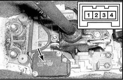
5. Disconnect the 4-pin connector from the locking mechanism (arrow).
6. Turn on the ignition. When connected to pin 2, the voltmeter should indicate battery voltage. If not, check the ignition switch circuit.
7. Switch off the ignition. When connected to pin 1, the voltmeter should indicate battery voltage. If not, check the 20A STOP fuse circuit.
Park position switch
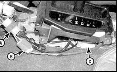
8. Determine the location of the switch connector (C - parking switch wire connector, B - lock mechanism, A - emergency lock switch).
9. Connect an ohmmeter to the switch socket contacts. The circuit must be closed.
10. Place the shift lever in any position other than park. The switch circuit must be open in all other positions.
11. Replace switch if necessary.
Replacing elements
Gear lever lock mechanism
1. Remove the center console.
2. Disconnect the wire from the mechanism.
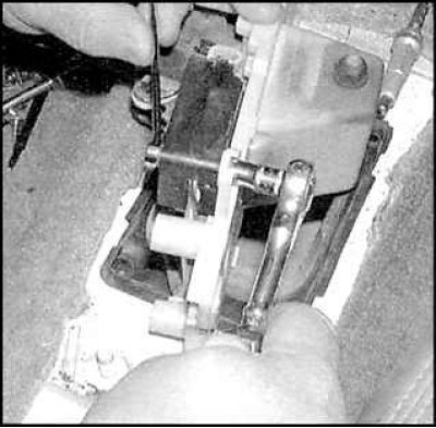
3. Remove the two screws and two nuts of the locking mechanism.
4. Remove the mechanism.
5. Installation is carried out in the reverse order of removal.
Ignition lock cable
6. Remove the center console.
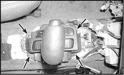
7. Remove the four screws for the gear lever position indicator and remove the indicator.
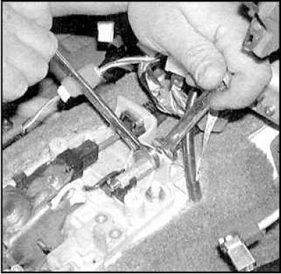
8. Loosen the cable locknut.
9. Disconnect the cable from the bracket.
10. Remove the lower part of the instrument panel.
11. Remove the top and bottom steering column covers.
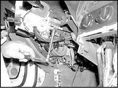
12. Unscrew the cable screw and remove its bracket.
13. Disconnect the cable from the ignition lock cylinder.
14. Remove the rope.
15. Installation is carried out in the reverse order of removal.
