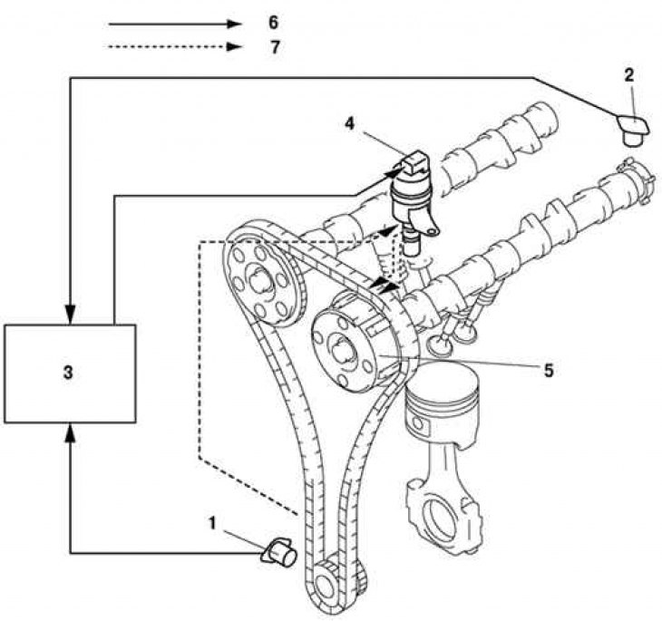
Pic. 2.31. Structural diagram of the valve timing mechanism: 1 - crankshaft position sensor; 2 - camshaft position sensor; 3 - block PCM; 4 - oil control valve (OCV); 5 - actuator for changing the valve timing; 6 – electrical signal; 7 - hydraulic pressure
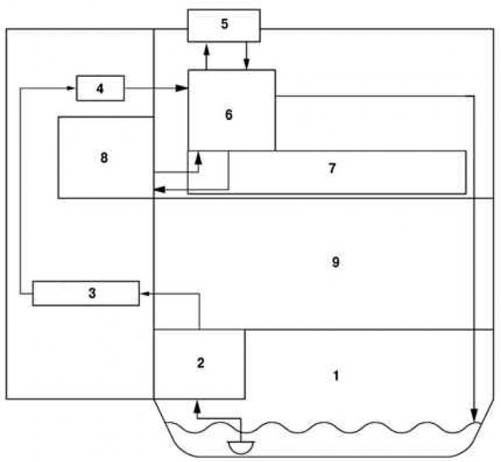
The variable valve timing mechanism consists of an actuator, an oil control valve (OCV), crankshaft position sensor, camshaft position sensor and PCM (pic. 2.31, 2.32 and tab. 2.12).

Pic. 2.32. Hydraulic pressure system block diagram: 1 - oil pan; 2 - oil pump; 3 - oil pipeline; 4 - oil filter; 5 - oil control valve (OCV); 6 - oil control valve adapter (OCV); 7 - camshaft; 8 - actuator for changing the valve timing; 9 - cylinder block
