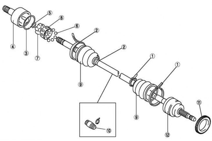
Pic. 3.159. Front Drive Shaft Components: 1 - cover clamp (from the side of the wheel); 2 - cover clamp (from the gearbox side); 3 - clamp; 4 - hinge body; 5 - retaining ring; 6 - balls; 7 - clip; 8 - separator; 9 - case; 10 – dynamic damper; 11 - the rotor of the sensor of the anti-lock braking system; 12 - shaft and ball joint
The components of the front drive shaft are shown in fig. 3.159.
Disassembly

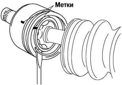
Pic. 3.160. Marking the joint housing and drive shaft
Mark the hinge body and shaft for reassembly (pic. 3.160).
Attention! Mark with paint; do not use a puncher.
Remove the clamp.
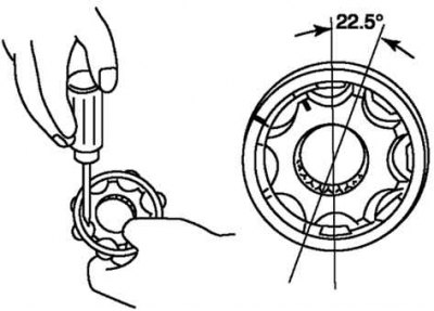
Mark the cage and separator.
Remove the circlip using circlip removal and installation pliers.

Pic. 3.161. Removing the separator
Rotate the cage approximately 30°and separate the cage and balls from the race (pic. 3.161).
Assembly

Pic. 3.162. Installing a dynamic damper
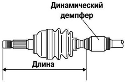
Establish a dynamic damper, as shown in Figure 3.162.
Standard length: 334.7 - 340.7 mm.
Install a new boot clamp on the dynamic damper.
Fill the case (from the side of the wheel) grease.
Note. The covers on the side of the wheel and on the side of the gearbox are different.
Attention! Do not touch the grease with your hands. Apply lubricant from the tube, do not allow contaminants to enter the case.
Attention! Grease quantity: 90-110 g (L8, LF left side), 105–125 g (L8, LF right side and L3)
Install the cover without removing the adhesive tape that was wrapped around the shaft splines during disassembly.
Remove the tape.

Pic. 3.163. Installing the separator and balls in the cage: 1 - separator; 2 - balls; 3 – a groove of a lock ring; 4 - clip
Align the marks and install the balls and separator in the cage in the direction shown in Figure 3.163.
Attention! Install the cage with the chamfer towards the circlip groove. If installed incorrectly, the drive shaft may disengage while driving.
Install a new retaining ring.
Complete hinge body and case (from the gearbox side) grease.
Grease quantity: 105-125 g (L8, LF left side), 120–140 g (L8, LF right side and L3).
Align the marks and install the housing on the shaft.
Install a new clip.
Install the cover.
Standard length, mm

Set the standard drive shaft length.
Release the air from the covers by prying up the edges of the smaller ends of the covers with a cloth-wrapped screwdriver.
Make sure the drive shaft length is within specification.
