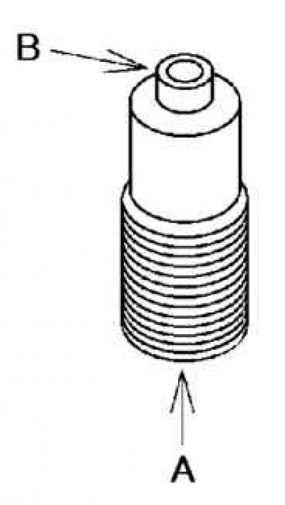
Pic. 2.161. Oil Spray Nozzle Valve Test Diagram
Apply compressed air to oil spray nozzle valve A and check that air flows through valve B (pic. 2.161).
If air does not pass, replace the oil spray nozzle valve.
Air pressure: 216–274 kPa.
Piston check
Attention! In normal practice, the piston, piston ring and connecting rod are not disassembled. When replacing a piston, the piston pin, piston ring and connecting rod are replaced together as a single piece.

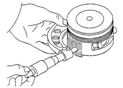
Pic. 2.162. Piston diameter measurement
Measure the outside diameter of each piston at a 90°right angle to the piston pin 10.0mm above the piston (pic. 2.162).
If the piston diameter is undersized, replace the piston, piston pin, piston ring and connecting rod assembly.
Piston diameter L8:
- 82.965–82.995 mm;
LF, L3, L3 (with a variable valve timing mechanism):
- 87.465–87.495 mm.
Measure the clearance between piston and cylinder.
If the value is not correct, replace the piston, piston pin, piston ring and connecting rod assembly.
- Normal clearance: 0.025–0.045 mm.
- Maximum gap: 0.11mm.

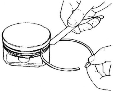
Pic. 2.163. Measuring the gap between the piston ring and the ring groove
Measure the clearance between the piston ring and the ring groove around the entire circumference of the piston (pic. 2.163).
If the clearance is greater than the maximum, replace the piston, piston pin, piston ring and connecting rod assembly.
Normal Clearance:
- top: 0.03–0.08 mm;
- second: by 0.03–0.07 mm;
- oil scraper: 0.03–0.07 mm.
Max Clearance:
- top: 0.17 mm;
- second, oil scraper: 0.15 mm.

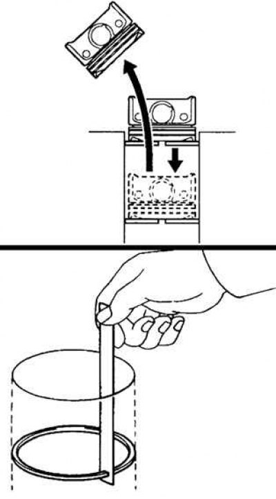
Pic. 2.164. Piston ring clearance measurement
Insert the piston ring into the cylinder and, pressing the ring with the piston, move it to the lowest point. Measure the gap in the lock of each piston ring with a feeler gauge (pic. 2.164).
If the clearance is greater than the maximum, replace the piston, piston pin, piston ring and connecting rod assembly.
Standard Clearance:
- top: 0.16–0.31 mm;
- second: 0.33–0.48 mm;
- oil scraper: 0.20–0.70 mm;
- maximum gap: 1.0 mm.
