Checking compressor wheel blades
1. Remove the engine trim panel.
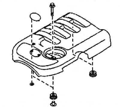
2. Remove the air duct located between the air filter housing and the turbocharger.
3. Inspect the compressor wheel blades with a mirror and a flashlight as shown in the figure and make sure that they are not damaged or deformed.
Note:
- Make sure the compressor wheel does not hit the turbocharger housing. If the wheel is rubbing, this may indicate an internal turbocharger failure.
- After replacing the turbocharger, check the intake and exhaust system components, as well as the lubrication system lines for damage.
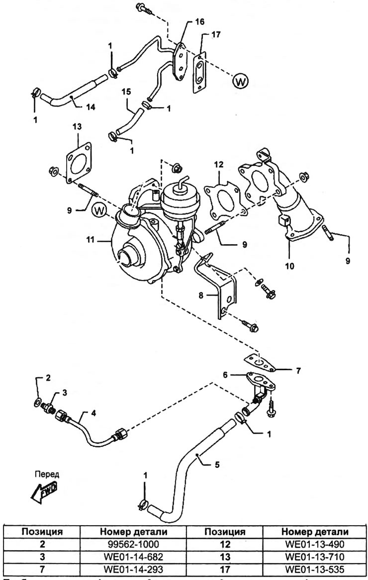
Turbocharger.
1 - collar,
2 - gasket,
3 - connector,
4 - engine oil supply hose,
5 - engine oil return hose,
6 - oil pipe,
7, 12, 13, 17 - gasket,
8 - turbocharger bracket,
9 - hairpin,
10 - a reception pipe of the exhaust system,
11 - turbocharger,
14, 15 - cooling system hoses,
16 - tube of the cooling system.
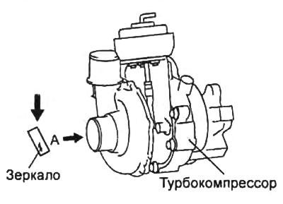
If there is damage to the compressor wheel blades, replace the turbocharger.
Turbine blade inspection
1. Remove the engine trim panel.
2. Remove the exhaust pipe from the exhaust system.
3. Inspect the turbine blades with a mirror and a flashlight as shown in the figure and make sure that they are not damaged or deformed.
Note:
- Make sure that the turbine wheel does not touch the turbocharger housing. If the wheel is rubbing, this may indicate an internal turbocharger failure.
- After replacing the turbocharger, check the intake and exhaust system components, as well as the lubrication system lines for damage.
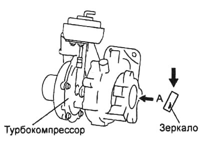
If there is damage to the turbine blades, replace the turbocharger.
Checking the turbocharger guide vane drive
1. Let the engine cool down.
2. Disconnect the vacuum hose from the actuator.
3. Connect the vacuum pump and check that the valve stem moves when the vacuum changes.
Underpressure:
- less than 14.2 kPa - the beginning of the movement
- more than 47.3 kPa - completely moved
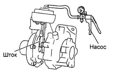
If operation differs from description, replace turbocharger.
Checking the vacuum control valve
1. Remove the valve.
2. Apply pressurized air to the port "A" valve and make sure that air flows out of the port "A" valve to port "IN".
3. Apply pressurized air to the port "IN" valve and make sure no air is leaking from the port "IN" valve to port "A".
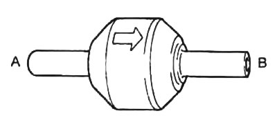
Otherwise, replace the vacuum control valve.
Checking the solenoid valve
Air Conductivity Test
1. Disconnect a wire from the negative plug of the storage battery.
2. Remove the boost pressure control solenoid valve.
3. Check for an open circuit in the valve. Use an ohmmeter to measure the resistance between the leads. If there is no continuity, replace the solenoid valve.
4. Make sure no air is escaping from the hole "A" to the hole "IN".
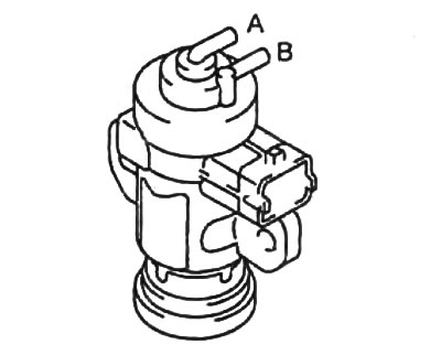
5. Apply battery voltage to terminal "A" valve, and the mass on the output "IN".
6. Make sure air is escaping from the hole "A" to the hole "IN".
If the described conditions are not met, replace the solenoid valve.
Resistance test
Using an ohmmeter, check the resistance between the valve terminals (at a temperature of 20 - 30°C).
- Resistance - 12.6 -15.6 Ohm
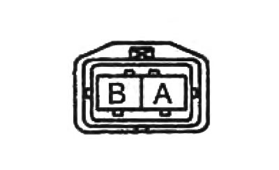
If the resistance is not as specified, replace the solenoid valve.
